Please wait...

Structural Engineering Test 1
Result
Structural Engineering Test 1
  • /

    Score
  • -

    Rank
Time Taken: -
  • Question 1/30
    1 / -0.33

    व्यास D के एक शाफ्ट को संयुक्त बंकन और ऐंठन आघूर्ण के तहत रखा जाता है। यदि बंकन आघूर्ण (M) और ऐंठन आघूर्ण (T) उस पर कार्यरत हैं, तो अधिकतम अपरुपण प्रतिबल ज्ञात कीजिए।
    Solutions

    संयुक्त बंकन आघूर्ण (M) और ऐंठन आघूर्ण (T) के तहत व्यास D के एक शाफ्ट के लिए,

    अधिकतम प्रमुख प्रतिबल 

    न्यूनतम प्रमुख प्रतिबल 

    अधिकतम अपरुपण प्रतिबल 
  • Question 2/30
    1 / -0.33

    If one of the ends of fixed beam sinks and causes the beam to rotate in a clockwise direction, then the moment induced at the ends of the beam will be
    Solutions

    As can be observed from the figure,

    Both ends will develop anticlockwise resistive moment against the deformation.

  • Question 3/30
    1 / -0.33

    Determine the direction of sway for the given rigid jointed frame.

    Solutions

    Sway in the rigid frame can be predicted either by computing the moment of resistance or by analysis.

    Method 1: Analysis by computing Moment of Resistance

    There are two columns in the frame i.e. AB and CD

    For the column AB ⇒ Moment of resistance against deformation = 

    For the column CD ⇒ Moment of resistance against deformation = 
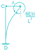
    Since both the columns have the same moment of resistance, the direction of sway cannot be predicted.

    Method 2: Practical Analysis

    Let’s divide the frame into two different portions, along the center line i.e. symmetrically.

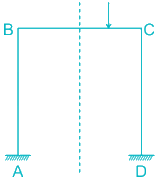
    Since the left portion of the frame doesn’t carry any external load, it’s kept out of the analysis. Taking the right side of the frame.

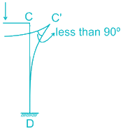
    Assume Frame sways in the right direction,

    But right sway would lead the rigid joint to form an acute angle between the two members, which is not possible.

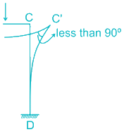
    Now, assume sway in the left direction,

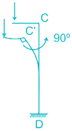
    Yes, left sway would maintain the right angle between the two members.

    ∴ The frame will sway in the left direction.
  • Question 4/30
    1 / -0.33

    The minimum diameter of rivet required to connect two plates of 8 mm and 10 mm is _______
    Solutions

    As per Unwin’s Equation for calculating the minimum diameter of rivet for connecting members,

  • Question 5/30
    1 / -0.33

    The maximum deflection of a fixed beam carrying concentrated point load is given as _______
    Solutions
  • Question 6/30
    1 / -0.33

    To generate the jth column of the flexibility matrix
    Solutions

    Stiffness Matrix Method

    1. This method is also known as displacement method or equilibrium method.

    2. It is suitable if static indeterminacy (Ds) > kinematic indeterminacy (D) for the structure.

    Stiffness is defined as Force required to produce unit displacement,

    K12 → Force at 2 due to unit displacement at 1

    Flexibility Matrix Method

    1. This method is also known as force method or compatibility method.

    2. It is suitable if kinematic indeterminacy (Dk) > static indeterminacy (Ds) for the structure.

    Flexibility is defined as Displacement caused due to unit Force.

    δ12 → Displacement at 2 due to Force at 1

    ∴ To generate a jth column of flexibility matrix a unit force is applied at coordinate j and the displacement are calculated at all coordinates.
  • Question 7/30
    1 / -0.33

    The correct value of θp for the given condition is ____

    Solutions

    Shear stress at any plane is given by,

    For shear stress at a plane being zero, τ = 0

  • Question 8/30
    1 / -0.33

    According to Tresca, yield locus is a/an
    Solutions

    Yield loci for two yield criteria in-plane stress as per Von Mises and Tresca Criteria is given below:

    ∴ According to Tresca, the yield is a hexagon.
  • Question 9/30
    1 / -0.33

    Rupture strength of the plate subjected to tensile loading is considered to be x% of its ultimate strength. What is the value of x as per IS 800-2007?
    Solutions

    As per IS 800 – 2007, rupture strength of the plate subjected to tensile loading is taken 90% of its ultimate strength.

    Bolts connected to plates tend to redistribute moments along the width of the plate. Thus, a moment at a critical location is reduced and redistributed.

    But to consider the factor of safety, for instance, if redistribution doesn’t occur ideally. IS Code has recommended taking rupture strength as 0.9 × fu (fu = ultimate strength of the material)

  • Question 10/30
    1 / -0.33

    Degree of redundancy for the given frame is ________

    Solutions

    Degree of Redundancy is also known as static indeterminacy.

    A structure is said to be statically indeterminate if the number of unknown forces of the given structure is more than the equilibrium equations available.

    Static Indeterminacy (D) = External static indeterminacy (Dse) + Internal static indeterminacy (Dsi) – Number of Force Releases

    Dse (External static indeterminacy) = Number of supports reactions – Number of equilibrium equation

    ∴ Dse (External static indeterminacy) = (2 + 3 + 1) – 3 = 3

    Dsi (Internal static indeterminacy) = 3 × C (for plane frame only)

    Where C = Number of cuts required to open a closed configuration

    Dsi = 3 × 4 = 12

    Force Release = m – 1 (for moment hinge only)

    Where m = Number of members connected to a Moment hinge

    Ds = 3 + 12 – 3 = 12
  • Question 11/30
    1 / -0.33

    Lueder Lines are _____
    Solutions
    Lueder Lines are 45° micro cracks developed in the neck zone due to shear stress acting on 45° planes, which is the resultant of tensile stress.
  • Question 12/30
    1 / -0.33

    A stone is thrown up at a slope of inclination θ and speed V from an inclined ground surface at an angle β from the horizontal. The stone reaches its greatest distance from the slope after a time of ___
    Solutions

    In the above figure, a stone is thrown at an angle β from an inclined sloping ground of θ.


    At the topmost vertical position, vertical component of velocity is zero.

  • Question 13/30
    1 / -0.33

    For a non-concurrent force system to be in equilibrium
    Solutions

    A body is said to be in equilibrium if the net forces acting on a body is zero and body remains in its stable state i.e. no displacement.

    Closure of Force Polygon Vector sum of all the forces is zero.

    Closure of Funicular Polygon No displacement caused to the action of forces

    ∴ For a non-concurrent force, a system to be in equilibrium both force polygon and funicular polygon must close.
  • Question 14/30
    1 / -0.33

    A circular lamina of radius R has a surface density  at a distance r from its centre. Its moment of inertia about an axis passing through its centre, perpendicular to its plane is ____
    Solutions

    Moment of inertia about an axis passing through its center, perpendicular to its plane is given by

  • Question 15/30
    1 / -0.33

    A prismatic bar of a square cross section of area (A) is axially loaded with a compressive load of P kN. Determine the normal stress acting on an element which makes 30° inclination with the vertical plane.

    Solutions

    Normal Stress on an inclined plane is given by,

  • Question 16/30
    1 / -0.33

    Match with and select correct answers using the options:

    List-I (Stiffener)

    List-II (Its location in plate girder)

    Transverse Stiffener

    Under Concentrated Load

    Horizontal Stiffener

    At Support

    End Bearing Stiffener

    Vertically along the span

    Load Bearing Stiffener

    Longitudinally in the compression zone

    Solutions

    Transverse Stiffeners are provided to increase buckling resistance of the web due to shear, It is provided vertically along the span.

    Horizontal Stiffener / Longitudinal Stiffener is designed to prevent web buckling due to bending compression.

    End Bearing Stiffeners are provided at the supports & Load Bearing Stiffeners are provided at the points of concentrated loads.

  • Question 17/30
    1 / -0.33

    Shear lag factor for calculating the net area of double angle connected back to back on the same side of gusset plate and tack riveted, as per working stress method is given by ________
    Solutions

    As per IS 800-1984 (Working Stress Method),

    Shear lag factor (K) for

    a) Single angle section connected to gusset plate by one leg only K = 

    b) Double angle connected back to back on the same side of gusset plate and tack riveted K = 

    As per IS 800:2007 (Limit State Method)

    Shear lag factor is replaced by the reduction factor for calculating reduced tensile strength of the outstanding leg of tensile member given by,

    `

  • Question 18/30
    1 / -0.33

    Economical depth of a plate girder as per Working Stress Method is given by ____ 

    Where M is the maximum moment in the plate girder, σ is allowable bending stress and t­ is the thickness of the web.

    Solutions

    Economical depth of Plate Girder as per Working Stress Method is given by

    Note:

    If the depth of girder is less than 750 mm, it is called shallow plate girder.

    If the depth of girder is more than 750 mm, it is called deep plate girder.

  • Question 19/30
    1 / -0.33

    If the coefficient of static friction us μ1 and that of dynamic friction is μ2, then from experiments  is ______
    Solutions

    μ1 (coefficient of Static Friction) is effective when the body is at rest and motion of the body is completely opposed by the Frictional Force.

    μ2 (coefficient of kinetic friction) is effective when the body is in motion and its motion is opposed to some small fraction by Friction Force.

    Coefficient of static friction is always greater than the coefficient of kinetic friction.
  • Question 20/30
    1 / -0.33

    Bending Moment Capacity of a square cross-section beam and a circular cross-section beam is given by Ms and M­c respectively. If both the beam is made up of the same material and have the same cross-sectional areas. Identify the appropriate option for the given condition.
    Solutions

    For the same cross-sectional area of the sections,

    Note:

    if beam is made up of same material and have same cross-sectional area
  • Question 21/30
    1 / -0.33

    A three hinged parabolic arch of rise 4 m is subjected to uniformly distributed load throughout its length, so that horizontal thrust is 10 kN. Due to an increase in temperature, if the crown rises by 10 cm. Then horizontal thrust _____
    Solutions

    For three hinged arches subjected to temperature change, change in horizontal thrust with respect to temperature change is given by,

    ∴ x percentage increase in the height of arch would result in x percentage decrease in the horizontal thrust and vice versa.

    Since the temperature is rising, the height of the arch will increase, and the horizontal thrust will decrease.

  • Question 22/30
    1 / -0.33

    Correct Influence Line Diagram for the member CG for the following given truss is

    Solutions

    Member CG is a diagonal member in the given truss.

    As a unit load moves along the truss AB,

    All the members present in the bottom beam as such AF, FG, GH, and HB are subjected to pure tension and all the members present in the upside beam as such CD and DE are subjected to pure compression.

    Member CG is a diagonal member where joint C is in compression and G is in tension.

    ⇒ The only diagram depicting the compression at C and tension at G is option D.

    Note: Shortcut for calculating the value of ILD diagram

    ILD Value of the ILD for member CG i.e. diagonal members of any truss is given by

    Where α → angle of inclination of a diagonal member w.r.t horizontal beam

    a → Horizontal distance of the location of a particular pin joint considered

    L → Horizontal length of the complete truss
  • Question 23/30
    1 / -0.33

    Which of the following option correctly depicts the conjugate beam for the given real beam.

    Solutions

    For converting real beam to conjugate beam,

     Real Condition 

     Condition in Conjugate Beam

     Fixed Support

     Free End

     Free End

     Fixed Support

     Internal Hinge

     Internal Hinged Support

     Internal Roller Support

     Internal Hinge

     Internal Hinged Support

     Internal Hinge

     Roller End Support

     Roller End Support

     Hinged End Support

     Hinged End Support

  • Question 24/30
    1 / -0.33

    Calculate support reaction at B (RB) for the given fixed beam, internally hinged under the load.

    Solutions

    As the beam is hinged at a distance of 3 meters from the support A, Let’s break the beam into two distinguished cantilever beams with load ‘X’ and ’20 – X’ respectively.

    Deflection for the hinged point would be equal for both of cantilever beam as shown in figure

    Deflection of the hinged end from cantilever Beam A = Deflection of the hinged end from cantilever Beam B

  • Question 25/30
    1 / -0.33

    Shear force diagram for the simply supported beam AB loaded with uniformly varying load is given by

    Solutions

    This option is directly eliminated, it signifies higher shear at support A as compared to support B, which is completely wrong.

    This option is directly eliminated, it signifies higher shear at support A as compared to support B, which is completely wrong.

    ∴ For gravity loading → Slope of the Shear Force Diagram should increase with the increasing intensity of loading.

    SFD in the above option shows decreasing slope value of SFD for increasing load intensity which is wrong.

    ∴ The above SFD is correct.

  • Question 26/30
    1 / -0.33

    Which the following graphs represent the allowable compressive stress (σac­) versus slenderness ratio (KL/r)

    Solutions

    Allowable axial compressive stress

    The allowable compressive stress is inversely proportional to the square of slenderness ratio.

    This shows a linear relationship between compressive strength and slenderness ratio which is wrong.

    This also shows a linear relationship between compressive strength and slenderness ratio which is wrong.

    This shows a finite compressive strength for zero slenderness ratio value, practically zero value of slenderness ratio is not possible and even if it’s possible, compressive strength should be infinite.

    ∴ This option is correct as it satisfies relationship as well as boundary conditions.
  • Question 27/30
    1 / -0.33

    Which one of the following is a graphical method to compute deflection of a truss joint?
    Solutions

    All of the above mentioned are the different method to compute deflection of a truss joint.

    However, Williot Mohr’s Diagram is the only graphical method to compute deflection.
  • Question 28/30
    1 / -0.33

    If the length of the welded joints for two plates is 700 mm for a plate of 8 mm and 10 mm welded together with weld size of 6 mm. What would be a reduction factor to be adapted for calculating weld strength?
    Solutions

    Reduction for the welded joint is considered only if,

    if the angle of fusion is 60°to 90° or if the angle of fusion is not given.

    Length of joint is 700 mm > 630 mm (150 × 4.2)

  • Question 29/30
    1 / -0.33

    Number of points of Contraflexure for the given set loading for the given frame is _______

    Solutions

    Point of Contraflexure ⇒ Point where the bending moment changes its sign is termed as a point of contraflexure.

    For the given frame,

    Fixed End Moment Direction is given by

    Therefore Fixed Moment Diagram is given by

    Assuming all beams to be simply supported, Bending Moment diagram is given as

    Now overlapping two diagrams,

    ∴ The number of point of contraflexure is 4.
  • Question 30/30
    1 / -0.33

    Calculate distribution factor for member OA for the shown figure.

    Solutions

    Joint O is connected to the four-member OA, OB, OC, and OD where far end is supported by vertical guided roller, vertical roller support, fixed support, and horizontal roller support respectively.

    Stiffness for OA is 

    Stiffness for OB is 0

    Stiffness for OC is 

    Stiffness for OD is 

    ∴ Stiffness for joint O is the sum of the stiffness for all the members connected to it.

    Stiffness for the joint O is 

User Profile
-

Correct (-)

Wrong (-)

Skipped (-)


  • 1
  • 2
  • 3
  • 4
  • 5
  • 6
  • 7
  • 8
  • 9
  • 10
  • 11
  • 12
  • 13
  • 14
  • 15
  • 16
  • 17
  • 18
  • 19
  • 20
  • 21
  • 22
  • 23
  • 24
  • 25
  • 26
  • 27
  • 28
  • 29
  • 30
Get latest Exam Updates
& Study Material Alerts!
No, Thanks
Click on Allow to receive notifications
×
Open Now