Please wait...

Mix Test Test 1
Result
Mix Test Test 1
  • /

    Score
  • -

    Rank
Time Taken: -
  • Question 1/20
    1 / -0.25

    In a belt drive system, when the speed of the belt increases
    Solutions

    Explanation:

    Power transmitted from one shaft to another shaft by means of Belts, ropes, chains, gears.

    A belt drive is a flexible drive. In flexible drives, there is an intermediate link such as a belt, rope, or chain between the driving and driven shafts.

    Since this link is flexible, the drives are called flexible drives.

    Features of Belt drive:

    • Belt drives can transmit power over a considerable distance between the axes of driving and driven shafts.
    • The operation of the belt drive is smooth and silent.
    • They can transmit only a definite load, which if exceeded, will cause the belt to slip over the pulley, thus protecting the parts of the drive against overload.
    • They have the ability to absorb shocks and damp vibrations.​


    Power Transmitted:

    Power transmitted by a rope or belt is given by a mathematical expression:

    P=(T1T2)V1000

    where: P is power in kW, T1 and T2 are tensions on the tight and slack side of the belt respectively in Newton, V is the linear velocity of the belt in m/s

    and V=π dN60

    where: d is the diameter of the pulley in m, and N is the RPM of the pulley.

    So from the power transmission equation velocity is directly proportional to the power so power transmission will increase if the speed of the belt increases.

  • Question 2/20
    1 / -0.25

    The total normal force (F) acting on the area of contact of disc clutch (Assuming uniform distribution of interface pressure) is:

    (Where P is the intensity of pressure, r0 and ri outer and inner diameter of disc respectively)
    Solutions

    Explanation:

    Let us consider a disc clutch,

    ris the outer radius of the disc

    ri is the inner radius of the disc

    P is the intensity of pressure

    F = normal force on the disc

    Normal reaction on the strip is given by dF=P(2πxdx)

    The total force is given by riroP(2πxdx)=2πP(r02ri22)=πP(r02ri2)

    Frictional force developed on the disc is given by dFf=μP(2πxdx)

    Frictional torque developed on the disc is given by dFf×x=μP(2πx2dx)

    Total Frictional Torque Tf=riroμP(2πx2dx)=μP2π(r03ri33)

    Mean radius of the clutch is given by Rm=23(r03ri3r02ri2)

    When Uniform wear theory is used

    P.r = C (constant)

    P1ri = P2ro = C

    F=2πC(rori)

    Tf=μCπ(ro2ri2)

    and Mean radius Rm=r0+ri2

  • Question 3/20
    1 / -0.25

    In the multiple disc clutch, if there are 6 discs on the driving shaft and 5 discs on the driven shaft, then the number of pairs of contact surfaces will be equal to
    Solutions

    Concept:

    Number of pair in contact, N = n1 + n2 – 1

    where n1 is the number of discs on driving shaft and n2 is the number of discs on the driven shaft.

    Calculation:

    Given:

    n1 = 6, n2 = 5

    N = 6 + 5 – 1 = 10
  • Question 4/20
    1 / -0.25

    Crushing efficiency of riveted joint is given by
    Solutions

    Explanation:

    Riveted joint:

    • The permanent joining of parts with the help of rivets is called a riveted joint.
    • Rivets are the cylindrical-shaped metal body used to leakproof the joining of dissimilar metals.
    • When two pieces of sheet joint with the help of riveted joint such that one sheet overlaps the other one then this type of joint is called lap joint.

    The efficiency of the riveted joint is defined as the ratio of the strength of the plate in an unpunched condition.

    η=StrengthofrivetedjointStrengthofunrivetedsolidplate

    As the strength of the riveted joint depends on the tearing strength, shearing strength or crushing strength of the joint, the efficiency can be tearing efficiency, shearing efficiency and crushing efficiency.

    Crushing efficiency: Crushing strength of the riveted joint/Strength of the unriveted solid plate

    ηc=CrushingstrengthStrengthofsolidplate

    The resistance offered by a rivet to be crushed is known as crushing resistance or crushing strength of bearing value of the rivet.

    Pc = ndtσc

    where n is no. of rivets.

     ηc=CrushingstrengthStrengthofsolidplate=n×d×t×σcp×t×σt


    Another two types of failure that occur in lap rivet joints:

    Tearing of the plate: If the force is too large that stress in the plate exceeds the allowable tensile stress of plate material, then the plate may fail in tension along the row.

    • Tearing efficiency: Tearing strength of the riveted joint/Strength of the unriveted solid plate

    ηt=TearingstrengthStrengthofsolidplateηt=(pd)tσtptσt=pdp

      Shearing of the rivet: When shear stress in the rivets exceeds the maximum allowable shearing stress then the shear failure of rivets takes place.

      • Shearing efficiency: Shearing strength of the riveted joint/Strength of the unriveted solid plate


      ηs=π4(σsσt)(d2pt)kn

      k is effective surface area (For double shear, k = 2), n is number of rivets in a pitch length

    • Question 5/20
      1 / -0.25

      In a pulley and belt drive, if m is mass of belt per unit length the velocity of belt for maximum power transmission is equal to
      Solutions

      Explanation:

      Centrifugal Tension: 

      Since the belt continuously runs over the pulleys, therefore some centrifugal force is caused, whose effect is to increase the tension on both the tight as well as the slack sides. The tension caused by the centrifugal force is called centrifugal tension (Tc

      Condition for Maximum power transmitted by the belt is: T = 3Tc i.e. power transmitted will be maximum when tension is equal to three-time centrifugal tension or it shows that when the power transmitted is maximum, 1/3rd of the maximum tension is absorbed as centrifugal tension.

      Power transmitted by a belt:

      P = (T– Ts).v

      where T the tension on the tight side (N), Ts is the tension on the slack side (N), V is the velocity of the belt in m/s.

      The belt velocity is given by, 

      Tc = mv2

      T3=mv2

      Therefore, v = Tcm=T3m

    • Question 6/20
      1 / -0.25

      Two steel trusses, XY and YZ of identical size supports a load of 200 N as shown in fig. The length of the truss is 1 m. The force in the truss XY in N is

      Solutions

      Concept:

      Lami's theorem states that if three co-planar, concurrent forces acting at a point are in equilibrium, each force is proportional to the sine of the angle between the other two forces.

      Consider three forces FA, FB, FC acting on a particle or rigid body making angles α, β and γ with each other.

      From Lami's theorem:

      Asinα=Bsinβ=Csinγ

      Calculation:

      Given:

      W = 200 N.

      Wsin120=Fxysin120=Fyzsin120

      200sin120=Fxysin120=Fyzsin120

      ∴ Fxy = Fyz = 200 N.

    • Question 7/20
      1 / -0.25

      While doing the analysis of a truss it was found that total member forces were 7 and the no of joints were 5. From these set of data one can conclude that the given truss is
      Solutions

      Concept:

      We know that for a truss if

      m – 2j + 3 = 0: Truss is stable / Determinate / Perfect,

      m – 2j + 3 < 0: Truss is superstructure

      m – 2j + 3 > 0: Truss is Unstable/Indeterminate

      where m = no. of member forces and j = number of joints.

      Calculation:

      Given:

      m = 7 and j = 5

      m – 2j + 3 = 7 – 2(5) + 3 = 0

      ∴ the given truss is stable.
    • Question 8/20
      1 / -0.25

      Coulomb friction is the friction between
      Solutions

      Explanation:

      Coulomb Law of Friction

      • Coulomb’s law of sliding friction can represent the most fundamental and simplest model of friction between dry contacting surfaces.
      • When sliding takes place, the coulomb law states that the tangential friction force is proportional to the magnitude of the normal contact force.
      • It is independent of relative tangential velocity.

      • When contacting bodies slide or tend to slide relative to each other tangential forces are generated.
      • These forces are usually referred to as friction forces.
      • Three basic principles have been established namely:
        • The friction force acts in a direction opposite to that of the relative motion between the two contacting bodies.
        • The friction force is proportional to the normal load on the contact.
        • The friction force is independent of a normal area of contact.
    • Question 9/20
      1 / -0.25

      In the case of flat collar pivot bearing, the frictional force in case of uniform wear can be assumed to be acting at
      Solutions

      Concept:


      Consider a single flat collar bearing supporting a shaft as shown in figure

      Let, r1 = External radius of collar, r2 = Internal radius of collar

      Considering uniform wear

      The load transmitted on the ring considering uniform wear is

      δW = 2πC × dr

      Integrating this equation from r2 to r1 to find the total load transmitted to the collar. We get,

      The total load transmitted to the collar, W = 2πC × (r1 - r2

      C=W2π × (r1  r2)

      Frictional torque on the ring,

      Tr = μ × δW × r = μ × 2πC × r × dr

      Integrating the above equation from r2 to r1, the total frictional torque on the bearing is given by

      T=2πμ × C(r12  r222)

      Substituting the value of C

      T=π × μ × W(r12  r22)2π(r1 r2)=12 × μW×(r1 + r2)

      Hence, In the case of flat collar pivot bearing, the frictional force in case of uniform wear can be assumed to be acting at (12) × (r1 + r2)

    • Question 10/20
      1 / -0.25

      In an inertial frame, a free particle:
      Solutions

      Explanation:

      The frame of reference: If we are observing any moving body or anybody at rest with respect to any moving object or from any object at rest then the object is called a frame of reference.

      There are two types of frame of reference:

      Inertial frame of reference:

      • The frame of reference having zero acceleration is called the Inertial frame of reference.
      • This frame of reference will be either at rest or will be moving with a constant velocity.
      • Newton’s law is valid in this frame of reference.
      • Example- A bus moving with constant velocity.

      The non-inertial frame of reference:

      • The frame of reference having non-zero acceleration is called a non-inertial frame of reference.
      • Newton’s law is not valid in this frame of reference.
      • For example: If we are observing an object from a freely falling object then this will be a non-inertial frame of reference because the freely falling body has some acceleration.
    • Question 11/20
      1 / -0.25

      If the two links have a turning as well as sliding motion between them, then the kinematic pair is known as-
      Solutions

      Explanation:

      Screw Pair:

      • If two mating links have a turning as well as sliding motion between them, they form a screw pair. this is achieved by cutting matching threads on the two links.
      • Eg. the lead screw and the nut of a lathe is a screw pair and a bolt with nut.

      Rolling pair: 

      • Two elements of a pair are connected in such a way that one rolls over another fixed link. 
      • Eg. Ball and roller bearings, rolling wheel on a flat surface etc.  

      Sliding pair:

      • When two links are so connected that one is constrained to have sliding motion relative to another.
      • Eg. crosshead and guide, rectangular rod in a rectangular hole in a prism.

      Turning pair:

      • When two links are so connected that one is constrained to turn or revolve about a fixed axis of another.
      • Eg. crankshaft turning in a bearing.

      Spherical pair: 

      • Two elements of a pair are connected in such a way that one element (with the spherical shape) turns or swivels about the other fixed element. 
      • Eg. the ball and socket joint, attachment of a car mirror, pen stand, etc.
    • Question 12/20
      1 / -0.25

      A car travelling at a constant speed of 36 km/hr in a circular path of radius 200 m, then normal acceleration and tangential acceleration in m/s2 is given by
      Solutions

      Concept:

      Normal acceleration and tangential acceleration along a curved road is given by

      Normal acceleration, an=v2R

      Tangential acceleration, at=R×α

      where v is the tangential velocity of the car, R is the radius of the curved road and α is the angular acceleration of the car.

      Calculation:

      Given:

      R = 200 m, v = 36 km/hr = 36×518 m/s = 10 m/s, α = 0 (since not mentioned)

      Normal acceleration,

      an=v2R=102200=0.5m/s2

      Tangential acceleration,

      at=R×α

      at=200×0

      at=0

      Hence, the value of an = 0.5 m/s2, and at = 0.

    • Question 13/20
      1 / -0.25

      A body Slipping on a rough horizontal plane moves with a deceleration of 5 ms-2. What is the coefficient of kinetic friction between the block and the plane? (g = 10 ms-2)
      Solutions

      Concept:

      Let Ff be the frictional force, N is the normal force and μk be the coefficient of kinetic friction.

      Newton’s Second Law:

      • The rate of change of linear momentum of a body is directly proportional to the external force applied on the body and this change takes place always in the direction of the applied force.

      F=ma

      a=Fm=Ffm=5

      We know that,

      Ff = μk N = μk × mg

      μk=Ffmg=Ffm.1g=ag=510=0.5

    • Question 14/20
      1 / -0.25

      According to the law of moments, if a number of coplanar forces acting on a particle are in equilibrium, then-
      Solutions

      Concept:

      Varignon’s Principle of moments (or the law of moments)

      It states, “If a number of coplanar forces are acting simultaneously on a particle, the algebraic sum of the moments of all the forces about any point is equal to the moment of their resultant force about the same point.”

      MO' = R × r = F1 × r1 + F2 × r2


      Lami's theorem

      Lami's theorem states that if three forces acting at a point are in equilibrium, each force is proportional to the sine of the angle between the other two forces. Consider three forces FA, FB, FC acting on a particle or rigid body making angles α, β, and γ with each other.

      Therefore, FAsinα=FBsinβ=FCsinγ

    • Question 15/20
      1 / -0.25

      Vee-belt E-type cross-sections are generally used in
      Solutions

      Explanation:

      Vee- Belt

      • The Vee belts are made up of rubber with fabric cords to transmits power and it's covered with a protective layer.
      • The cords transmit the force from the driver to the driven pulley, thereby transmit the power.
      • Vee belts are widely used in industry and automobiles because of their power transmitting capacity.
      • The wedge shape of the belt increases the area of contact with the pulley thereby increasing more friction, which makes it carry more power without slip.


      Vee belt cross-sections

      • There are different sizes of Vee belt cross-sections named A, B, C, D, and E (based on the width of the belts).
      • These are standard sizes manufactured by belt manufacturers.


      • As we move from A to E, The power transmitted by the Vee belt drive increases. Hence Vee-belt drive with E-type cross-sections is used in the heavy-duty machine.


      Vee belts are preferred over the flat belts the reasons follow.

      • Power transmitted is more due to wedging action in the grooved pulley.
      • Higher velocity ratio (Upto 10) can be obtained.
      • Vee-belt drive is more compact, quiet and shock absorbing.
      • The Vee belt drive is positive because the slip is negligible.
      • Clean and requires no lubrication.
      • They are efficient - performing with an average of 94 - 98 % efficiency.
    • Question 16/20
      1 / -0.25

      When trying to turn a key into a lock, we apply a
      Solutions

      Explanation:

      Since we are simply rotating the key along its axis and during the process we apply force through both of our thumb and index finger in the opposite direction.

      This equal and opposite force is called a couple and it does not give any translatory effect so the key remains stationary in the groove.

      • One can think that we are also pushing the key into the hole so why not considering that, the reason is simple because the question is asking about the turning phase only.
      • One can mark the answer as coplanar force, but it does not say anything about the magnitude of the force and we have a better option available which says these forces are equal and opposite, hence the couple is more correct.
    • Question 17/20
      1 / -0.25

      Which is not a type of Rolling contact bearings:
      Solutions

      Explanation:

      Bearing: It is a mechanical element that permits relative motion between two parts with minimum friction.

      Functions of bearing:

      • Free rotation of shaft with minimum friction.
      • Supports shaft and holds in the correct position.
      • Bears force that acts on the shaft and transmits to the foundation.
      • Bearings are classified into two types :
      1. Sliding contact bearing (Journal bearings)
      2. Rolling contact bearing.

      Sliding contact bearing it is classified as 

      • Thick film lubrication
      • Thin-film (zero films) lubrication bearing.

      Roller contact bearings

      Roller contact bearings are the bearings that use spherical balls, or some other type of roller between the stationary and the moving elements. 

      These bearings are also called anti-friction bearing.

      Roller contact bearings are classified into two types:

      • Ball Bearings are used to take heavy as well as high-speed loads. It is classified into the following types.
        • Deep groove ball bearing
        • Angular ball bearing
        • Self align ball bearing
        • Thrust ball bearing
      • Roller Bearing
        • Cylindrical Roller Bearing
        • Taper Roller Bearing
        • Spherical Roller Bearing
        • Needle Roller Bearing
    • Question 18/20
      1 / -0.25

      If the momentum of a body increases from 10 units to 25 units in 5 sec, then the force acting on it is
      Solutions

      Concept:

      The correct answer is 3 units.

      • Newton's 2nd law of motion says the rate change of momentum is called force.
      • The equation for the change in momentum is F ×  t = m ×  Δv
      • If the momentum of a body increases from 10 units to 25 units in 5 seconds.
      • Then the change in the momentum is 25 – 10 = 15 units in time 5 seconds.
      • So the Force extract from this is 15/5 = 3 Newton.

      • Momentum is a vector quantity that is the product of the mass (weight) of a particle and its velocity (speed).
        • SI unit: kilogram meter per second (kg⋅m/s).
      • A spinning object has angular momentum.
      • An object travelling with a velocity has linear momentum.
      • A change in momentum may result from an acceleration or a force or an impulse.
    • Question 19/20
      1 / -0.25

      The radius of gyration ‘K’ of the plane figure is determined by the relation
      Solutions

      Explanation: 

      In the case of the plane area.

      The formula of moment inertia in terms of the radius of gyration is given as follows :

      I = A × K2, where I is the area moment of inertia and A is the area of the plane body

      k=IA

      In case of mass moment of Inertia

      The radius of gyration: It is the radial distance from the point to the axis of rotation where the whole mass of the body is supposed to be concentrated so that the moment of inertia of the system is the same as the given situation.

      I = M × K2

      Fig. A represents the moment of inertia for the body of mass M about the axis passing through it.

      Fig. B represents the moment of inertia for point mass (having the same mass as the original body) placed at distance K from the axis of rotation.

      I1 = I2

      K=IM

      where, I = Moment of inertia, M = Concentrated mass at point (Same as original mass) and K = Radius of gyration (Distance from the point mass to the axis of rotation)

      Moment of Inertia: The moment of inertia is the sum of the products of the mass of each particle in the body with the square of its distance from the axis of rotation. Also termed as the angular mass or rotational inertia. Denoted by I, then

      I = Σ M R2

      Where I is the moment of inertia of the body, M is the mass of the body, R is the radius.

    • Question 20/20
      1 / -0.25

      The efficiency of a riveted joint is equal to Pt = Tensile strength of the plate, Ps = Shear Strength of the plate, Pc = Crushing strength of the plate and P is the stregth of unriveted solid plate.
      Solutions

      Concept:

      The efficiency of riveted joints id defined as the ratio of strength of riveted joint to the strength of unriveted solid plate. The strength of the rivested joint is the lowest value of Ps, Pt and Pc.

      Strength of solid plate is given by 

      P = ptσt

      Therefore the efficiency is given by 

      η = least of Pt,Ps and PcP

      (i) Tensile strength of Plate between rivets

      Due to the tensile stresses in the main plates, themain plate or cover plates may tear off across a row of rivets as shown in Fig:

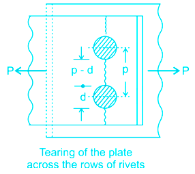
      Pt is the tensile strength of plate between rivets and is given by

      The resistance offered by the plate against tearing is known as tearing resistance

      Pt=Atσt=(pd)t.σt

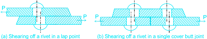
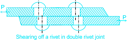
      (ii) Shear Strength of Rivet

      Shearing of the rivets: The plates which are connected by the rivets exert tensile stress on

      the rivets, and if the rivets are unable to resist the stress, they are sheared off.

      The resistance offered by a rivet to be sheared off is known as shearing resistance or shearing strength or shearing value of the rivet

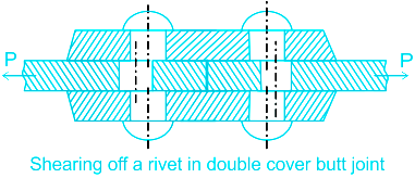
      d = Diameter of the rivet hole, τ = Safe permissible shear stress for the rivet material, and n = Number of rivets per pitch length

      Shearing resistance or pull required to shear off the rivet per pitch length:

      Ps=n×π4d2×τ{SingleShear}

      Ps=2n×π4d2×τ{DoubleShear}

      So, the strength equation for the rivet in the double-riveted joints is given by:

      Ps=2×π4d2×τPs=π2d2τ

      (iii) Crushing Strength Pof the plate is given by 

      Pc = d x t x σc x n

      d = Diameter of the rivet, t= thickness of the plate, σc = compressive strength of the plate.

    User Profile
    -

    Correct (-)

    Wrong (-)

    Skipped (-)


    • 1
    • 2
    • 3
    • 4
    • 5
    • 6
    • 7
    • 8
    • 9
    • 10
    • 11
    • 12
    • 13
    • 14
    • 15
    • 16
    • 17
    • 18
    • 19
    • 20
    Get latest Exam Updates
    & Study Material Alerts!
    No, Thanks
    Click on Allow to receive notifications
    ×
    Open Now