Please wait...

AC Circuits, Generators & Transformers Test - 1
Result
AC Circuits, Generators & Transformers Test - 1
  • /

    Score
  • -

    Rank
Time Taken: -
  • Question 1/10
    1 / -0.25

    At resonance the impedance is:
    Solutions

    CONCEPT:

    • The ac circuit containing the capacitorresistor, and inductor is called an LCR circuit.
    • For a series LCR circuit, the total potential difference of the circuit is given by:

    V=VR2+(VLVC)2

    Where VR = potential difference across R, VL =  potential difference across L and VC =  potential difference across C

    • For a series LCR circuitImpedance (Z) of the circuit is given by:

    Z=R2+(XLXC)2
    Where R = resistance, XL =induvtive reactance and XC = capacitive reactive

    EXPLANATION :

    • Resonance of an LCR circuit is the frequency at which capacitive reactance is equal to the inductive reactance, Xc = XL, then the value of impedance is given by

    Z=R2+(XLXC)2

    Z=R2+0

    Z=R

    • At resonance, the value of impedance is purely resistive. Hence, option 1 is the answer
  • Question 2/10
    1 / -0.25

    Peak value of AC current is 4√2, RMS current is :
    Solutions

    The correct answer is option 4) i.e. 4 A

    CONCEPT:

    • Peak value: The maximum value attained by the alternating current during a cycle is called its peak value. Considering alternating current as a sinusoidal wave, the peak value is its amplitude or crest value.

    • RMS value: RMS current is that value of steady current which when flowing through a given resistance for a given period of time, produces the same quantity of heat like that of an alternating current flowing through the same resistance and for same time period.
      • It is also known as the effective value of alternating current.

    The RMS current Irms is related to the peak current I0 as:

     Irms=I02

    CALCULATION:

    Given that:

    ​The peak value of current, I0 = 4√2

    RMS value of current, Irms=I02=422= 4 A

  • Question 3/10
    1 / -0.25

    For a series RLC circuit driven by voltage v = vmsinωt, the current is given by i = im sin(ωt + φ) and the power factor = __________
    Solutions

    Concept:

    For an RLC circuit, the power factor is given as cosine of phase angle

    i.e., cosϕ=RZ

    Here, R is resistance and Z is the impedance of RLC combination if the amount of current is i = im sin(ωt + φ) and v = vmsinωt

    Where,

    i, v = RMS value of current  and voltage respectively 

    φ = Phase angle

    ω = angular frequency 

    im, vm = maximum value of current and voltage 

    Explanation:

    From the above explanation, we can see that for an RLC combination the power factor is given as 

    cosϕ=RZ

    Hence option 3 is correct among all

  • Question 4/10
    1 / -0.25

    An RLC series circuit is supplied by an alternating voltage source of 200sin100πt V. The circuit parameters are as follows

    R=100Ω,L=2πH,C=100πμF.

    Find the impedance of the circuit.
    Solutions

    CONCEPT:

    • The ac circuit containing the capacitorresistor, and inductor is called an LCR circuit.
    • For a series LCR circuit, the total potential difference of the circuit is given by:

    V=VR2+(VLVC)2

    Where VR = potential difference across R, VL =  potential difference across L and VC =  potential difference across C

    • For a series LCR circuitImpedance (Z) of the circuit is given by:

    Z=R2+(XLXC)2
    Where R = resistance, XL =induvtive reactance and XC = capacitive reactive

    • The resonant frequency of a series LCR circuit is given by

    ν=12πLC

    CALCULATION:

    As we know that,

    Inductive Reactance (XL) = ωL

    • Given alternating voltage

    ⇒ V = 200 sin 100 πt

    Comparing with standard voltage equation

    ⇒ V = Vm sin ωt

    We get,

    ⇒ ω = 100π

    Now, inductive reactance 

    XL=100π×2π

    ⇒ XL = 200 Ω

    • Capacitive reactance 

    XC=1ωC

    Xc=1100π×100π×106

    ⇒ Capacitive reactance (Xc) = 100 Ω

    • The impedance of the circuit is given by

    Z=R2+(XLXC)2

    Z=1002+(200100)2

    Z=10000+10000 =104+104 =2×10⁴

    Z=1002 = 100 × 1.414 = 141.4 Ω

  • Question 5/10
    1 / -0.25

    In wattless current phase difference between current and voltage is :
    Solutions

    CONCEPT:

    • Wattless current: The current in AC circuit is said to be wattless current if the average power consumed in such circuit corresponds to zero and such current is also called idle current

    The average power of an AC circuit is given by:

    Pav = ErmsIrms cos ϕ

    The current Irms can be resolved into two components i.e. along with parallel and perpendicular components.

    • The Component Irms cosϕ is along Erms . Here the phase angle between Irms cosϕ and Erms is zero.

    Pav = Erms (Irms cos ϕ) cos 0 =  Erms Irms cos ϕ

    • The Component Irms sinϕ is normal to Erms . Here the phase angle between Irms sinϕ and Erms is π/2.

    Pav = Erms (Irms sin ϕ) cosπ2 = 0

    • We call the component Irms sin ϕ as the idle or wattles current because it does not consume any power in a.c. circuit.

    EXPLANATION:

    • Component Irms sinϕ is normal to Erms . As the phase angle between Irms sinϕ and Erms is π/2.

    Pav = Erms (Irms sin ϕ) cosπ2 = 0

    • We call the component Irms sin ϕ as the idle or wattles current because it does not consume any power in a.c. circuit. This happens in a purely inductive or capacitive circuit in which current and voltage differ by a phase difference of π /2.
    • Hence option 2 is correct.

    NOTE:

    • The wattless current is possible in a circuit where resistance is zero.
  • Question 6/10
    1 / -0.25

    The frequency of an alternating current is 50 Hz. In how much time does it reverse its direction?
    Solutions

    CONCEPT:

    • Alternating current: The electric current whose direction changes periodically is called electric current.
    • Frequency (ν): The number of waves that pass a given point per second is called frequency.
      • The unit of frequency is vibration per second or Hertz.
    • Time period (T): The time taken to complete one full oscillation or cycle by the Wave is called time period.

      • The SI unit of the time period is second (s).

    The relationship between time period and frequency is given as:

    Time period (T) = 1/ν 

    EXPLANATION:

    Given that:

    Frequency (ν) = 50 Hz

    Time period (T) = 1/ν = 1/50 sec

    So the time taken to complete one oscillation = 1/50 sec

    Since this time is time for one complete oscillation, but the current changes its direction at midpoints (half-wave) itself. 

    So time for reverse the direction = T/2 = 1/100 sec

    Hence option 2 is correct.

  • Question 7/10
    1 / -0.25

    The ratio of the number of turns in primary and secondary coils of transformer is 1: 20. The ratio of the currents in the primary and the secondary coils will be
    Solutions

    Concept:

    • Transformer: An electrical device that is used to transfer electrical energy from one electrical circuit to another is called a transformer.
      • In a transformer, there are two coils- The primary coil (P) and secondary coil (S).

    There are two types of transformer:

    • Step-up transformer: The transformer which increases the potential is called a step-up transformer.
      • The number of turns in the secondary coil is more than that in the primary coil.
    • Step-down transformer: The transformer which decreases the potential is called a step-down transformer.
      • The number of turns in the secondary coil is less than that in the primary coil

    In a transformer, the voltage in secondary is calculated by:

     NsNp=VsVp=IpIs

    Here, Np and Ns are the numbers of turns in the primary and the secondary coils respectively and Vp and Vs are the RMS voltages across the primary and secondary respectively and Ip and Is are primary and secondary currents.

    Calculation:

    Given that:

    The ratio of turns of coil Np / Ns = 1 / 20

    We know that

    NsNp=IpIs

    201=IpIs

    ⇒ IP : Is = 20 : 1

  • Question 8/10
    1 / -0.25

    An AC generator consists of a coil of 800 turns and a cross-sectional area of 2.5 m2. The coil is placed in a uniform magnetic field of 0.05 T and it is rotated with an angular speed of 50 rad/sec. If the resistance of the coil is 200 Ω, then find the maximum current produced by the generator:
    Solutions

    CONCEPT:

    AC Generator:

    • An AC generator is a device that converts mechanical energy into electrical energy and generates alternating current.
    • It works on the principle of electromagnetic induction i.e., when a coil is rotated in a uniform magnetic field, an alternating emf is induced in the coil.
    • The main components of the AC generator are:
      1. Armature
      2. Strong field magnet
      3. Slip rings
      4. Brushes
    • When the armature coil ABCD rotates in the magnetic field provided by the strong field magnet, it cuts the magnetic lines of force.
    • Thus the magnetic flux linked with the coil changes and hence induced emf is set up in the coil.
    • The direction of the induced emf or the current in the coil is determined by Fleming’s right-hand rule.
    • The current flows out through the brush B1 in the first half of the revolution and through the brush B2 in the next half revolution of the coil.
    • This process is repeated. Therefore, emf produced is of alternating nature.
    • The coil of the AC generator is rotated with a constant angular speed ω, the angle between the magnetic field vector B and the area vector A of the coil at any instant t is θ. Then,

    ⇒ θ = ωt

    The flux linked with the coil at any time t is,

    ⇒ ϕ = BA.cosθ

    • From Faraday’s law, the induced emf at any time t for the rotating coil of N turns is given as,

    ⇒ ϵ = NBAω.sin(ωt)

    • If the resistance of the coil is R, then the induced current at any time t for the rotating coil of N turns is given as,

    I=ϵR=NBAωsin(ωt)R

    CALCULATION:

    Given A = 2.5 m2, N = 800 turns, ω = 50 rad/sec, B = 0.05 T, and R = 200 Ω

    Where A = area of the coil, N = number of turns, R = resistance, ω = angular speed of coil, and B = magnetic field

    • We know that the maximum current induced in the AC generator is given as,

    Imax=NBAωR

    Imax=800×0.05×2.5×50200

    ⇒ Imax = 25 A

    • Hence, option 1 is correct.
  • Question 9/10
    1 / -0.25

    In a series LCR circuit the voltage across the resistance, capacitance and inductor is 10 V each. If the capacitor is short circuited, the voltage across the inductor will be
    Solutions

    Concept:

    LCR Circuit: The ac circuit containing the capacitor, resistor, and inductor is called an LCR circuit.
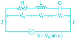
    For a series LCR circuitImpedance (Z) of the circuit is given by:

    Z=R2+(XLXC)2
    Where R = Resistance, XL = Inductive reactance, XC = Capacitive reactive

    If the voltage drop across the three is the same, then R = XL = XC 

    Calculation:

    Given:

    VR = VL = VC = 10 V

    As the voltage drop across the three is the same, then R = XL = XC

    If the capacitor is shorted then

    R = XL 

    Impedance, Z=R2+(XLXC)2

    Z=R2+(R0)2

    Z = R√2

    So the current in the circuit

    I = VZ=10R2

    Also, VL = IXL 

    VL = 10R2×R   (∵ XL = R)

    VL = 102  V

    Additional Information Power factor (Cos Φ): The ratio of the true power to the apparent power of an a.c. the circuit is called the power factor.

    • Its value varies from 0 to 1.

    The power factor (P) of a series LCR-circuit is given by:  

    cosΦ=RZ=RR2+(XLXC)2

    Where R = resistance, Z = Impedance, XL = Inductive reactance and XC = Capacitive reactance

  • Question 10/10
    1 / -0.25

    An RLC circuit has a resonance frequency of 160 kHz and a Q-factor of 100. Its bandwidth is
    Solutions

    Concept:

    The quality factor Q is defined as the ratio of the resonant frequency to the bandwidth.

    Q=frBW=1RLC

    fr = Resonant frequency

    BW = Bandwidth of the resonant circuit

    Calculation:

    Given fr = 160 kHz

    Q = 100

    BW=frQ

    Bandwidth = 160 kHz100=1.6 kHz

    The sharpness of the resonance in RLC series resonant circuit is measured by the quality factor and is explained in the figure shown below:

    A close up of a mapDescription automatically generated


    Observations:

    • Less the Bandwidth, more the Quality factor.
    • More the Bandwidth, less is the Quality factor.
    • For the above figure, B2 > B1, so Q2 < Q1
User Profile
-

Correct (-)

Wrong (-)

Skipped (-)


  • 1
  • 2
  • 3
  • 4
  • 5
  • 6
  • 7
  • 8
  • 9
  • 10
Get latest Exam Updates
& Study Material Alerts!
No, Thanks
Click on Allow to receive notifications
×
Open Now