Please wait...

Turbo Machinery Test 1
Menu grid icon
Result Result point icon
Turbo Machinery Test 1
  • Goals icon

    /

    Score
  • Trophy icon

    -

    Rank
White alarm icon Time Taken: -
Result frame illustration
  • Question 1/10
    1 / -0.25

    An impulse hydraulic turbine:
    Solutions

    Explanation:

    • In Impulse Turbine, the available hydraulic energy is first converted into kinetic energy by means of an efficient nozzle.
    • The high-velocity jet issuing from the nozzle then strikes a series of suitably shaped buckets fixed around the rim of a wheel.
    • The buckets change the direction of the jet without changing its pressure. The resulting change in momentum sets buckets and wheel into rotary motion and thus mechanical energy is made available at the turbine shaft. 
    • Important impulse turbines are: Pelton wheel, Turgo - impulse wheel, Girad turbine, Banki turbine and Jonval turbine etc., Pelton wheel is predominantly used at present.
    • Whereas In Reaction Turbine, a part of the total available hydraulic energy is transformed into kinetic energy before the water is taken to the turbine runner. A substantial part remains in the form of pressure energy.
  • Question 2/10
    1 / -0.25

    Which hydraulic turbine is more efficient at part load operation?
    Solutions

    Kaplan turbines maintains a high efficiency over the part load operation.

    Since a Kaplan turbine has adjustable or movable blades hence for a required discharge the movable blades can be adjusted so that the losses due to the flow separation can be minimized.

    Note:

    Kaplan turbine is an axial flow reaction turbine in which the water flows parallel to the axis of rotation of the shaft. For Kaplan, both the kinetic and potential energy is available at inlet.

    Kaplan turbine has adjustable moving blades and so it is also known as variable pitch propeller turbine.

    Axial flow reaction turbine has less number of blades and thus the friction loss will be lesser and it can work on low head producing high discharge and high specific speed. But this is susceptible to cavitation.

  • Question 3/10
    1 / -0.25

    In a parson's reaction turbine, when α1 is the angle with the  direction of motion of the blade at which steams enters the blade, then the maximum efficiency of the turbine is given by
    Solutions

    Explanation:

    Reaction turbine

    In the reaction turbine, a number of fixed and moving blades are assembled alternately inside the casing.

    The fixed blade acts as nozzles for each stage, and are attached to the turbine casing, whereas the moving blades are fixed with the rotor.

    Parson reaction turbine

    • In Parson's reaction turbine, the steam is first expanded by a ring of fixed blades and then directed to a ring of moving blades, whereas, the direction of steam is altered for the first stage.
    • The steam leaving the first stage enters the second ring of fixed moving blades, where the further expansion of the steam takes place.
    • This continuous until its pressure drop to the exhaust pressure.
    • The drop in pressure causes an increase in the velocity of steam in moving blades.
    • As a result of this, the relative velocity of steam at the outlet (Vr2) is greater than the relative velocity at the inlet (Vr1).
    • In Parson reaction turbine, fixed and moving blades are symmetrical i.e. the exit angle of the moving blade is equal to the exit angle of the fixed blade (β= α1) and the inlet angle of the moving blade is equal to inlet angle of the fixed blade (β= α2).
    • Since blades are symmetrical, velocity diagram is also symmetrical. In such a case, the degree of reaction is 50%
    • In parson's reaction turbine the power is obtained by an impulsive force of the incoming steam and small reactive force of the outing steam.
    • The blades receive the incoming steam, below is the velocity diagram of blades.

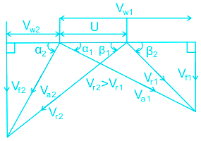
    where above symbols depict:

    = Tangential velocity of blades

    va1,va2 = the absolute velocity of steam at inlet and outlet of a moving blade.

    vw1, vw2 = the velocity of whirl at inlet and outlet of a moving blade.

    vf1, vf2 = the velocity of flow at the inlet and outlet of a moving blade.

    vr1, vr2 = the relative velocity of steam at inlet and outlet of a moving blade.

    α1, α2 = outlet, and inlet angle of a fixed blade.

    β1, β2 = inlet, and outlet angle of a moving blade.

    Maximum efficiency of Parson's reaction turbine is given by:

     \((\eta_b)_{max}=\frac{{2{{\cos }^2}\alpha_1 }}{{1 + {{\cos }^2}\alpha_1 }}\)

  • Question 4/10
    1 / -0.25

    In a reaction turbine, the draft tube is used to

    Solutions

    Explanation:

    Draft Tube: The draft tube is a conduit that connects the runner exit to the tailrace where the water is being finally discharged from the turbine. It is used with reaction turbines only.

    The draft tube has two purposes as follows if

    i) It permits a negative or suction head to be established at the runner exit, thus making it possible to install the turbine above the tailrace level without loss head.

    ii) It converts a large proportion of velocity energy rejected from the runner into useful pressure energy.

    A draft tube is made divergent so as to reduce the velocity at the outlet to a minimum. Therefore, a draft tube is basically a diffuser and should be designed properly with the angle between the walls of the tube to be limited to about 8 degrees so as to prevent the flow separation from the wall and to reduce accordingly the loss of energy in the tube.

  • Question 5/10
    1 / -0.25

    In Kaplan turbine runner, the number of blades is generally of the order _____.
    Solutions

    Explanation:

    Kaplan turbine:

    • In Kaplan turbine, water flows parallel to the axis of rotation of the shaft, hence it is called axial flow turbine.
    • Head at the inlet of the turbine is the sum of pressure energy and kinetic energy.
    • During the flow of water through the runner, a part of pressure energy is converted into kinetic energy.
    • It indicates that the Kaplan turbine is a reaction turbine. When the vanes on the hub are adjustable, the turbine is known as the Kaplan turbine.
    • When vanes are not adjustable, the turbine is called the propeller turbine. Kaplan turbine components are shown in the figure below.

    • Kaplan turbine has adjustable runner blades. Kaplan Turbine has a very small number of blades 3 to 8.


    • Francis Turbine has a very large number of blades 16 to 24
  • Question 6/10
    1 / -0.25

    Two Pelton wheels A and B are having same specific speed and are working under the same head. Wheel A provides 900 kW at 800 rpm. If wheel B produces 100 kW, then its rpm will be
    Solutions


    Concept:

    Specific speed: It is defined as the speed of a similar turbine working under a head of 1 m to produce a power output of 1 kW. The specific speed is useful to compare the performance of a various types of turbines. The specific speed differs for a different types of turbines and is the same for the model and actual turbine.

    \({N_s} = \frac{{N\sqrt P }}{{{H^{\frac{5}{4}}}}}\)

    Calculation:

    Given, PA = 900 kW, NA = 800 rpm, PB = 100 kW

    For the same specific speed and working under the same head i.e.

    Ns1 = Ns2 and H1 = H2

    \(N\sqrt P = constant\)

    \(∴ {N_A}\sqrt {{P_A}} = {N_B}\sqrt {{P_B}}\)

    \({N_B} = 800\sqrt {\frac{{900}}{{100}}}= 2400\;rpm\) 

  • Question 7/10
    1 / -0.25

    Cavitation in a hydraulic reaction turbine is most likely to occur at the turbine’s ____. 

    Solutions

    Explanation:

    • Cavitation is the phenomenon of formation of vapour bubbles of a flowing liquid in a region where the pressure of the liquid falls below the vapour pressure of the fluid and sudden collapsing of these bubbles in the region of higher pressure.
    • In reaction turbines, the pressure of the working fluid changes gradually as it passes through the runner along with the change in its kinetic energy based on absolute velocity due to the impulse action between the fluid and the runner.
    • At the exit of the rotor, the pressure of the working fluid is lowest, if the pressure falls below the vapour pressure of working fluid then cavitation may occur at the outlet of the rotor.
    • Due to cavitation, the metal of the runner vanes is gradually eaten away, which results in lowering the efficiency of the turbine.

    Cavitation in Centrifugal Pump: 

    • In centrifugal pumps, the cavitation may occur at the inlet of the impeller of the pump or at the suction side of the pumps, where the pressure is considerably reduced.
    • Cavitation also occurs in reciprocating pumps if there is a high-velocity suction or discharge.
  • Question 8/10
    1 / -0.25

    What is the number of buckets on the runner of a Pelton turbine if the jet ratio is 12?

    Solutions

    Explanation:

    Number of buckets on a runner: \(Z = 15 + \frac{D}{{2d}}\) 

    Given: Jet ratio = 12 i.e D/d =12

    Now,

    Number of buckets on a runner = 15 + 6

    ∴ Number of buckets = 21


    Design parameters of Pelton wheel turbine:

    1. Velocity of jet: at inlet \({V_1} = {C_V}\sqrt {2gH} \) where Cv = coefficient of velocity = 0.98-0.99

    2. Velocity of wheel: \(u = \emptyset \sqrt {2gH} \) where φ is the speed ratio = 0.43-0.48

    3. Angle of deflection: is 165° unless mentioned.

    4. Pitch or mean diameter: D can be expressed by \(u = \frac{{\pi DN}}{{60}}\)

    5. Jet ratio: \(m = \frac{D}{d}\) (12 in most cases/calculate), d = nozzle diameter or jet diameter

    6. Number of buckets on a runner: \(Z = 15 + \frac{D}{{2d}}\) (Tygun formula) or, \(Z = 5.4\sqrt m \), m = 6 to 35

    7. Number of Jets: obtained by dividing the total rate of flow through the turbine by the rate of flow through single jet. The number of jets is not more than two for horizontal shaft turbines and is limited to six for vertical shaft turbines.

    8. Size of bucket: length of bucket L = 2.5d, width of bucket B = 5d, depth of bucket Db = 0.8d 

  • Question 9/10
    1 / -0.25

    The specific speed (Ns) of a hydropower station depends on

    1. Power produced (P)

    2. Speed of the turbine (N)

    3. Head (H)
    Solutions

    Specific speed: It is defined as the speed of a similar turbine working under a head of 1 m to produce a power output of 1 kW. The specific speed is useful to compare the performance of the various type of turbines. The specific speed differs for the different type of turbines and is the same for the model and actual turbine.

    \({N_s} = \frac{{N\sqrt P }}{{{H^{\frac{5}{4}}}}}\)

    Explanation:

    From the above expression, the specific speed of a hydropower station depends on

    • Power produced (P)
    • Speed of the turbine (N)
    • Head (H)


    Following are the range of specific speed of different turbines

    • The specific speed of Pelton wheel turbine (single jet) is in the range of 10-35
    • The specific speed of Pelton wheel turbine (multiple jets) is in the range of 35-60
    • The specific speed of Francis turbine is in the range of 60-300.
    • The specific speed of Kaplan/propeller turbine is greater than 300.
  • Question 10/10
    1 / -0.25

    _______ turbine is an inward flow reaction turbine with the radial discharge at outlet.
    Solutions

    Concept:

    Impulse Turbine: If at the inlet of the turbine, the energy available is only kinetic energy, the turbine is known as impulse turbine. e.g. a Pelton wheel turbine.

    Reaction Turbine: If at the inlet of the turbine, the water possesses kinetic energy as well as pressure energy, the turbine is known as a reaction turbine. e.g. e Francis and Kaplan turbine.

    Tangential flow turbines: In this type of turbines, the water strikes the runner in the direction of the tangent to the wheel. Example: Pelton wheel turbine

    Radial flow turbines: In this type of turbines, the water strikes in the radial direction. accordingly, it is further classified as

    • Inward flow turbine: The flow is inward from periphery to the centre (centripetal type); Example: old Francis turbine
    • Outward flow turbine: The flow is outward from the centre to periphery (centrifugal type); Example: Fourneyron turbine


    Axial flow turbine: The flow of water is in the direction parallel to the axis of the shaft. Example: Kaplan turbine and propeller turbine

    ∴ Francis turbine is a radial inward flowing reaction turbine.

Close button icon
User Profile
-

Correct (-)

Wrong (-)

Skipped (-)


  • 1
  • 2
  • 3
  • 4
  • 5
  • 6
  • 7
  • 8
  • 9
  • 10
Mockers logo Get latest Exam Updates
& Study Material Alerts!
No, Thanks
Arrow pointer icon
Click on Allow to receive notifications
Notification bell icon ×
Open Now