Verify mobile number to view the solution
Solutions
Two wattmeter method:
The connection diagram using wattmeters is shown below.
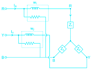
\({W_1} = {I_R}{V_{RB}}\cos \left( {{I_R} \ ^\wedge{V_{RB}}} \right)\)
\({W_2} = {I_Y}{V_{YB}}\cos \left( {{I_Y}^\wedge{V_{YB}}} \right)\)
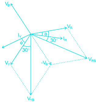
From the phasor diagram
\({I_R}^\wedge{V_{RB}} = 30 - ϕ \)
\({I_Y}^\wedge{V_{YB}} = 30 + ϕ \)
\({W_1} = {I_R}{V_{RB}}\cos \left( {30 - ϕ } \right)\)
\(\Rightarrow {W_1} = {V_L}{I_L}\cos \left( {30 - ϕ } \right)\)
\({W_2} = {I_Y}{V_{YB}}\cos \left( {30 + ϕ } \right)\)
\(\Rightarrow {W_2} = {V_L}{I_L}\cos \left( {30 + ϕ } \right)\)
\({W_1} + {W_2} = {V_L}{I_L}\left[ {\cos \left( {30 - ϕ } \right) + \cos \left( {30 + ϕ } \right)} \right]\)
\(= \sqrt 3 {V_L}{I_L}\cos ϕ\)
⇒ Total three-phase power \( = {\rm{\;}}{{\rm{W}}_1} + {{\rm{W}}_2} = \sqrt 3 {V_L}{I_L}\cos ϕ \)
Total three-phase power is the sum of two wattmeters.
\({W_1} = {V_L}{I_L}\cos \left( {30 - ϕ } \right)\)
\({W_2} = {V_L}{I_L}\cos \left( {30 + ϕ } \right)\)
\({W_1} - {W_2} = \sqrt 3 {V_{ph}}{I_{ph}}\sin ϕ\)
\(\sqrt 3 \left( {{W_1} - {W_2}} \right) = 3{V_{ph}}{I_{ph}}\sin ϕ \)
Reactive power \(= \surd 3\;\left( {{W_1}-{W_2}} \right)\)
Reactive power is equal to √3 times the difference between the readings of the two wattmeters.
\({W_1} + {W_2} = 3{V_{ph}}{I_{ph}}\cos ϕ\)
\(\sqrt 3 \left( {{W_1} - {W_2}} \right) = 3{V_{ph}}{I_{ph}}\cos ϕ \)
\(\Rightarrow ϕ = {\tan ^{ - 1}}\left( {\frac{{\sqrt 3 \left( {{W_1} - {W_2}} \right)}}{{{W_1} + {W_2}}}} \right)\)
Power factor \(= cos\;ϕ\)
\(cosϕ = \cos \left[ {{{\tan }^{ - 1}}\left( {\frac{{\sqrt 3 \left( {{W_1} - {W_2}} \right)}}{{{W_1} + {W_2}}}} \right)} \right]\)
Points to remember:
- If the power factor is between zero and 0.5 or the power factor angle is between 60° and 90° then one of the wattmeters shows a negative value.
- If ϕ = 60° or power factor is 0.5 then one of the wattmeter shows zero reading


 Time Taken: -
 Bank
Bank


 SSC
SSC


 Railway


 State
State


 Other
Other


 Teaching


 Insurance


 Medical


 Engineering


 Defence


 GATE
GATE


 NTA CUET

 UPSC
UPSC

 MBA Entrance


 LAW
LAW

 ReNEET UG 2026
 CUET UG 2026
 UP Police Constable 2026
 SSC Selection Post (Phase 14) 2026
 SSC GD 2025-26
 RRB NTPC 2026
 SSC CGL Tier-I 2026
 SSC JE 2026
 UPSC (CSE) 2026
 SBI PO Prelims 2026
 SSC Steno Grade C & D 2026
 SBI Clerk Prelims 2026
 IBPS PO Prelims 2026
 IBPS Clerk Prelims 2026
 SSC CPO Tier I 2026