Please wait...
/
-
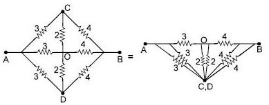
The equivalent resistance between A and B will be (in ?)
Verify mobile number to view the solution
As C & D are at same potential by symmetry of circuit °
It is balanced wheat-stone bridge Hence the circuit has equivalant resistance 7/3 Ω
As shown in figure, a permanent magnet and current carrying coil are placed. If the coil is moved towards magnet, then current in coil (Magnet is symmetrical) :
No change in the flux occurs due to the described motion of the magnet. Hence no current will be induced in the coil.
Current through resistance woll be from
A to B if
20 – ε > 2 ⇒ ε < 18
and from
B to A if 20 – ε < 2
A super conducting loop having an inductance 'L' is kept in a magnetic field which is varying with respect to time. If is the total flux, e = total induced emf, then:
A battery of internal resistance ' r ' and e.m.f. ε is connected to a variable external resistor AB. If the sliding contact is moved from A to B, then terminal potential difference of battery will :
V = E - i r. Now, if we go from A → B, then resistance of the circuit increases, ' i ' decreases
∴ V increases
Figure shows a conducting horizontal rod of resistance r is made to oscillate simple harmonically with a fixed amplitude in a uniform and constant magnetic field B, directed inwards. The ends of rod always touch two parallel fixed vertical conducting rails. The ends of rails are joined by an inductor and a capacitor having self inductance and capacitance 1/π Henry and 1/π farad respectively. The amplitude of current in the circuit depends on the frequency of oscillation of rod. The amplitude of the current will be maximum when the time period of rod is : (do not consider self inductance anywhere other than in the inductor)
Here oscillating rod is an AC source because emf induced in it is (vBℓ) ; which varies sinusoidally because v varies sinusoidally.
Maximum current will flow through the circuit under resonance condition. Therefore time period of oscillation of rod is
In the figure shown the equivalent capacitance between 'A' and 'B' is :
A very small circular loop of area 5 × 10⁻⁴ m2 and resistance 2 ohm is initially concentric and coplanar with a stationary loop of radius 0.1 m. If one ampere constant current is passed through the bigger loop and the smaller loop is rotated about its diameter with constant angular velocity ω. The current induced (in ampere) in the smaller loop will be :
The capacitor shown in figure 1 is charged completely by connecting switch S to contact a. If switch S is thrown to contact b at time t = 0, which of the curves in figure 2 above represents the magnitude of the current through the resistor R as function of time t ?
The potential difference across completely charged capacitor is V. As the switch is pushed to b, the initial current in the resistor R is V/R. Hence J is the correct curve.
At a given instant the current and self induced emf in an inductor are directed as shown in figure. If the induced emf is 17 volt and rate of change of current is 25 kA/s the correct statement is :
Correct (-)
Wrong (-)
Skipped (-)


 Time Taken: -
 Bank
Bank


 SSC
SSC


 Railway


 State
State


 Other
Other


 Teaching


 Insurance


 Medical


 Engineering


 Defence


 GATE
GATE


 NTA CUET

 UPSC
UPSC

 MBA Entrance


 LAW
LAW

 ReNEET UG 2026
 SSC Selection Post (Phase 14) 2026
 RRB NTPC 2026
 SSC CGL Tier-I 2026
 SSC JE 2026
 SBI PO Prelims 2026
 SSC Steno Grade C & D 2026
 SBI Clerk Prelims 2026
 IBPS PO Prelims 2026
 IBPS Clerk Prelims 2026
 SSC CPO Tier I 2026
 NDA II 2026
 CDS II 2026